A data centre is an electrical and mechanical plant with a room attached. Everything the equipment draws as power leaves as heat, so power, cooling and space are one design problem. The answer starts with how the operator will run the facility: the load today, the growth plan, and how maintenance happens without stopping service.
Power
Utility service, switchgear, UPS and standby generation sized to a confirmed brief, not to a generic label.
Heat
Cooling plant and heat rejection that remove what the equipment gives off, and can be maintained without taking the room down.
Change
Space, structure and capacity planned in stages, so the second and third phases fit without rebuilding the first.
When the grid goes dark
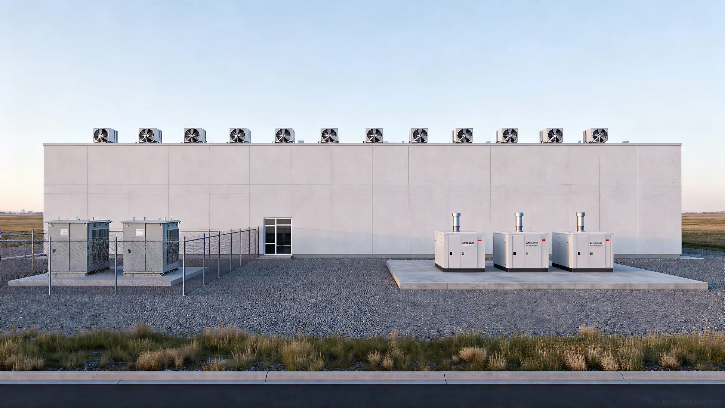
From the outside, a quiet box on the prairie.
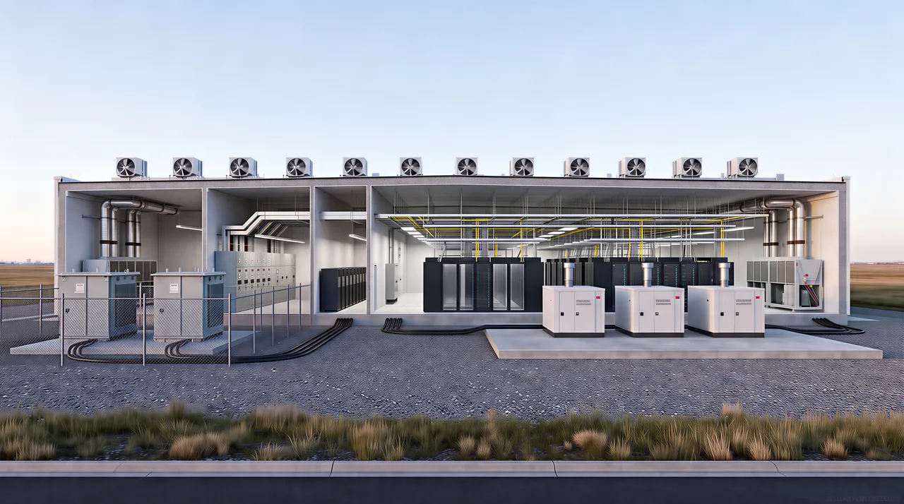
Inside, power and cooling arrive by more than one path.
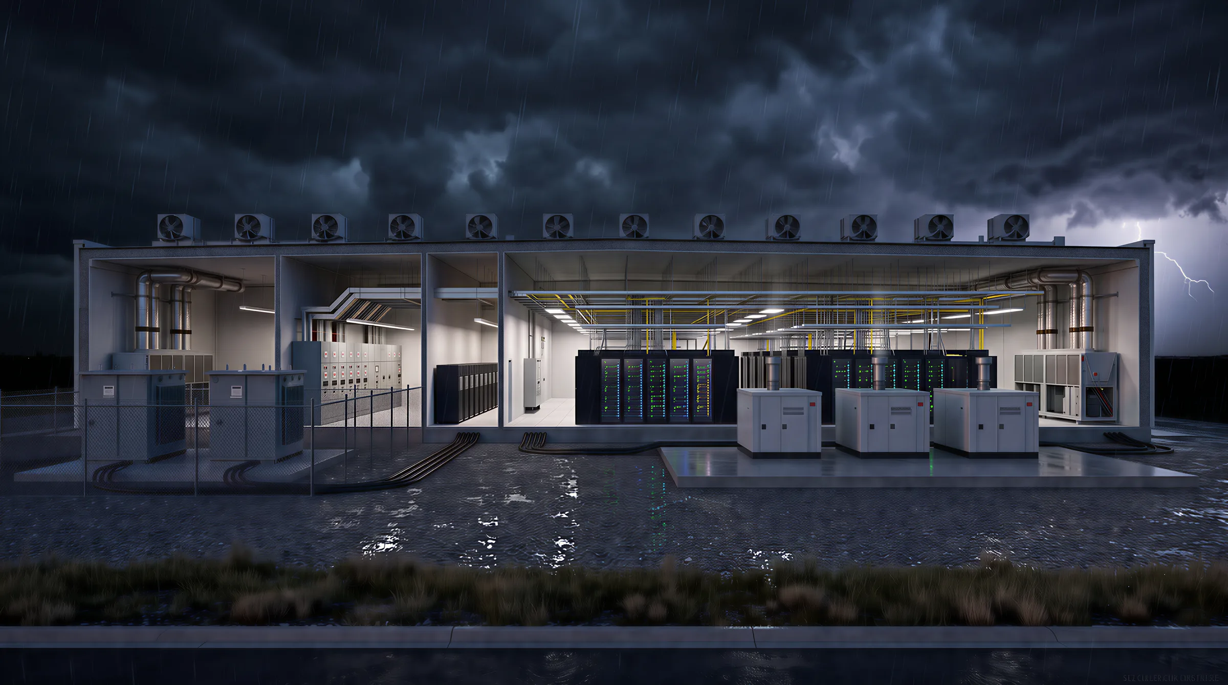
When the grid goes dark, the racks stay lit.
How it stays on
Power in, heat out, never off.
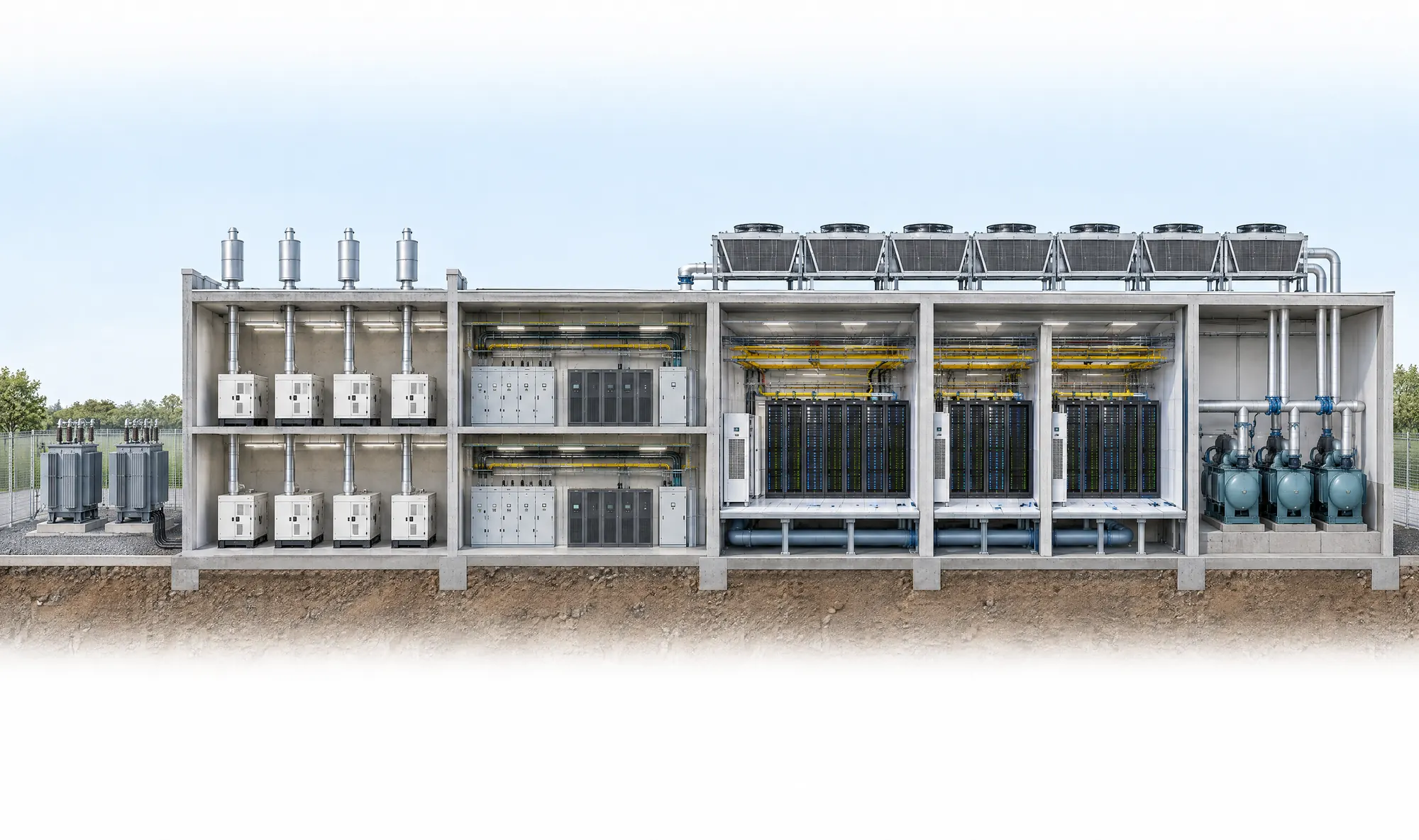
Choose how much redundancy the brief asks for, fail a path, lose the utility, then grow the facility in phases. A conceptual diagram, not any facility’s design: no capacities, efficiency figures or availability ratings are shown or implied.
Try it
Phase onePhase twoFull build
3 halls · 3 UPS modules · 3 cooling units
Section through a data facility. Power comes in from two utility transformers through switchgear, UPS modules with standby generators, and distribution to three halls of racks. Heat leaves through cooling units in each hall, a chilled-water loop under the raised floor, the chillers in the cooling plant and the dry coolers on the roof. Redundancy can be a single path, a spare module, or two independent paths, and the facility is built in three phases.
Service continuesNormal operation. The utility feeds the racks through the UPS, the generators wait on standby, and the cooling removes the heat.
Full build. All three halls, with the electrical and cooling plant added in the same steps the owner’s growth plan called for.
Power in
The utility feeds switchgear. Behind it a UPS carries the racks through a short interruption, and generators take over for a longer one. Distribution then reaches each hall of racks.
Utility service
Switchgear
UPS and generators
Distribution
Heat out
Cooling units take heat from the racks into a chilled-water loop. The cooling plant moves it outdoors, where heat-rejection equipment gives it to the air.
Cooling units
Cooling plant
Heat rejection
Redundancy is a decision
A single path is simplest and has no fallback. A spare module covers a failed unit. Two independent paths cover a whole chain. Each costs more space and money, so the operator’s brief sets the level, not a default.
Single path
N+1
Two independent paths
Growth in phases
The building, the structure and the conduits are sized for the final facility; the equipment is added in steps as load arrives. The first phase stays running while the next is installed.
Reserved space
Conduits in place
Equipment in steps
What to ask
What to ask your engineer.
Six questions that turn a vague brief into a design.
What load, and when?
Separate what is needed on day one from what is allowed for later. Power and cooling should be designed from the same list.
Which failures must it ride through?
Ask for the redundancy approach in words: what fails, what takes over, what still stops service. The diagram above is that conversation.
How is it maintained without stopping service?
Maintenance paths, isolation points and spare capacity decide whether a unit can be taken out while the room runs.
Where does the heat go?
Heat rejection needs outdoor space, airflow, noise control and a route for the pipes; ask for them early.
Utility intake documentation and load calculations come first and take time. At 9929 Swanson Street, our electrical engineers prepared them to BC Hydro requirements for a new 1,600 A, 600 V service.
Why we do it. How we approach it. What we bring to a critical facility.
WhatHowWhy
Why
Because someone depends on the room staying on.
A company’s systems or a community’s services run in it. The engineering is how that dependence is made safe.
How
By agreeing the brief before choosing the equipment.
Load, growth, maintenance and the operating conditions the operator needs are written down first. Electrical, mechanical and structural design then follow the same assumptions, with the IT designers, the utility and the testing team.
What
Building engineering for critical facilities.
Utility service and distribution design, power-system studies, standby and UPS planning, HVAC and cooling coordination, and structural support for heavy equipment. Specialist IT design and availability certification are assigned to named specialists.
Who we work with
One brief, many specialists.
A data-centre project is a conversation between the operator, the utility, the IT designers and the building team. We keep the building side coherent.
Owners & IT operators
Establish the IT load, growth assumptions, maintenance approach and operating conditions before selecting infrastructure.
Architects & specialist designers
Coordinate equipment layout with structural loads, cooling, electrical distribution and service space.
Contractors & testing teams
Define the interfaces, test sequences and review responsibilities across vendors and building systems.
Building owners with technical rooms
Investigate existing power, cooling and structure before adding load or changing how a room is kept running.
Related work
Related work, clearly labelled.
Electrical and mechanical work for facilities that operate around the clock, and utility service design for heavy power users.
Our published portfolio does not yet include a completed data centre. These projects are related electrical and building work, described only as their records describe them.
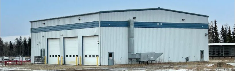
A new electrical service to two adjacent industrial sites off Airport Road: site planning to BC Hydro requirements, load calculations and utility intake documentation, coordinated with FSJ Quality Electric for approval. It is the first link in the chain above, a confirmed load in writing for the utility.
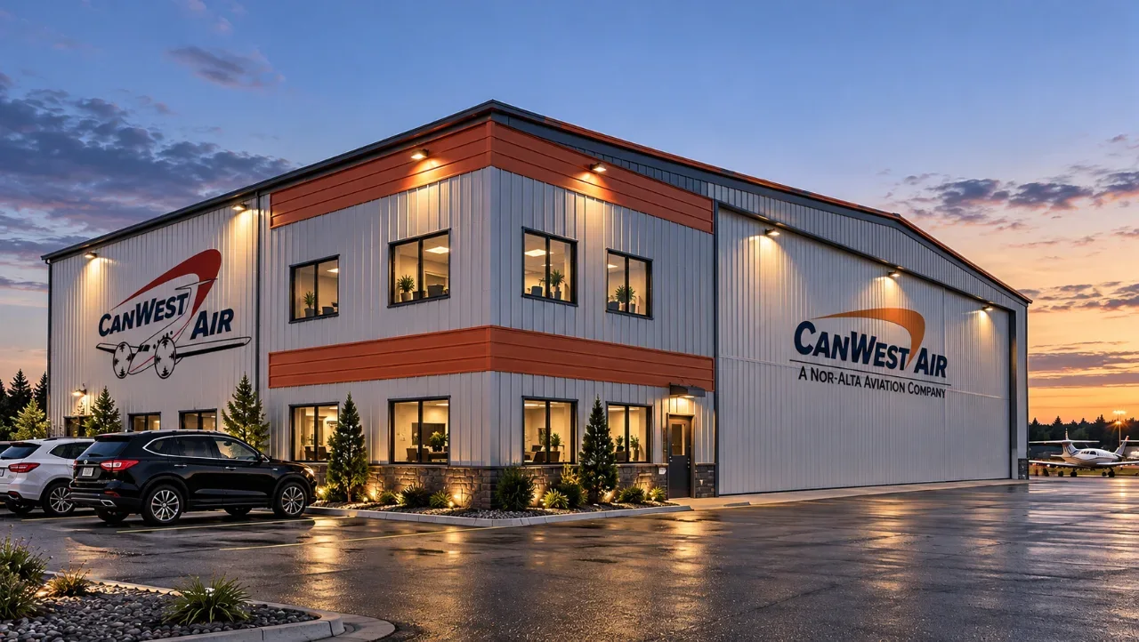
The base for a fixed-wing air-ambulance service at the Medicine Hat airport, sized for two King Air aircraft and including living quarters and offices for crews who work round the clock. Design Works provided mechanical and electrical engineering and energy modelling.
Design Works’ role
Mechanical Engineering / Electrical Engineering / Energy Modelling
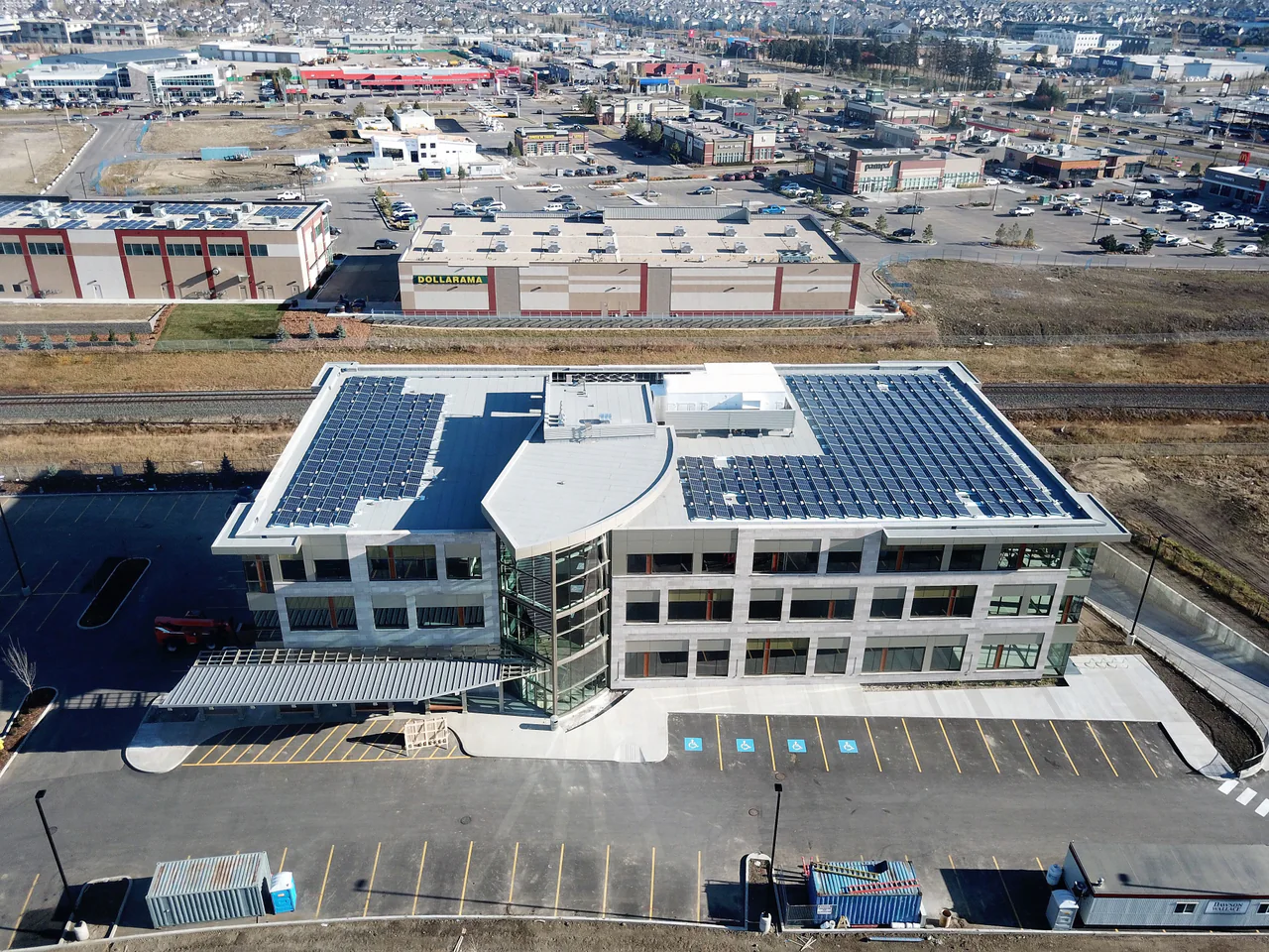
Several buildings at Gateway Boulevard and Ellerslie Road in Edmonton for Cameron Developments, with a solar energy system designed in collaboration with Kuby Renewable Energy. Design Works provided sustainable design and electrical engineering.
Not one we have published, and we say so plainly. Our published work includes utility service design for heavy electrical users and mechanical and electrical engineering for round-the-clock facilities. For a data-centre brief we would scope the team around the specialists the project needs.
Do you design to a tier or availability rating?+
Ratings come from the owner’s brief and are certified by named specialists. We design the electrical, mechanical and structural systems to the agreed brief and coordinate with the certifier.
What do you need to start a feasibility conversation?+
The intended IT loads, the growth plan, the site or building information, the environmental requirements and the operating strategy. They let us identify capacity questions, investigations and specialist inputs.
Can you upgrade an existing server or technical room?+
We begin with an assessment of what exists: the utility service, the distribution, the cooling and the structure. That shows what can be added before load or continuity arrangements change.
Who designs the IT infrastructure?+
Specialist IT designers do. We coordinate their equipment layout and requirements with the power, cooling, structure and space of the building.